
Introduction 1-1 Introduction 1 Scope of this Manual This manual includes model/kit information, specifications, fundamental disassembly/reassembly procedures, maintenance, alignment, troubleshooting and all theory, schematic diagrams.ġ-2 Introduction Model Numbering System Position 1 - Type of Unit M = Mobile Radio Positions 2 & 3 - Model Series Position 4 - Frequency Band 66 to 88MHz 136 to 174MHz 146 to 174MHz 403 to 470MHz 450 to 512MHz 806 to 870MHz 896 to 941MHz Valu. 1-5 Kit-to-Model Structure for 800 and 900 MHz Radios. X List of Tables Kit-to-Model Structure for VHF and UHF Radios. Ix List of Figures RF and Power Connector Openings. Viii SB9600, Simplified Schematic for Charts 1-10 & 1-11. Vii Bootstrap Microprocessor Operation.7-16 Audio and Signalling Circuits.

5-4 Remove the Transceiver Board E XCEPT 800 MH Z AND. Vi Remove the PA Shield L OW AND M ID P OWER M ODELS.

Iv LP Gas Warning It is mandatory that radios installed in vehicles fuelled by liquefied petroleum gas conform to the National Fire Protection Association standard NFPA 58, which applies to vehicles with a liquid propane (LP) gas containe. The radio may switch into transmit mode, immedi. Iii Operational Safety Warnings For vehicles equipped with Electronic Ignition Systems, check the vehicle service manual for warnings about the use of two-way radio equipment in the vehicle. Laws in the United States and other countries preserve for Mo.
#Motorola mcs 2000 control head bracket software
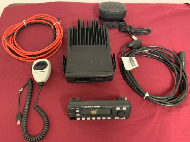
Ii Computer Software Copyrights The Motorola products described in this manual may include copyrighted Motorola computer programs stored in semiconductor memories or other media. MCS 2000 Mobile Radio Service Instructions Volume 1 Non-Frequency Range Specific 68P81083C20-A, Issued: 02.97.


 0 kommentar(er)
